

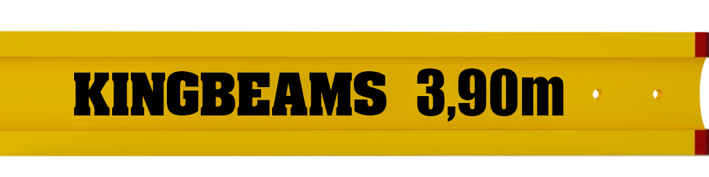

h20-Ahşap kalıp kirişleri
Güvenli ve güvenilir bir yapısal kiriş sağlamak üzere tasarlanan H20 Ahşap kirişler, düşük ağırlıkta yüksek form stabilitesi sağlar.

Kolay Entegrasyon
Birincil ve ikincil kirişler, masa sistemindeki döşemelerin altlık kalıbını oluşturmak veya yüksek yük taşıyan destek veya şev güvertelerinde daha fazla güvenlik sağlamak için H20 Evrensel Kelepçe ile 90 ° açıyla birbirine bağlanır.


Mükemmel Uyumluluk
Benzersiz bağlantı aksesuarları sayesinde H20 Ahşap kirişler duvarlarda mükemmel bir ikincil destek oluşturur
Yüksek Form Kararlılığı
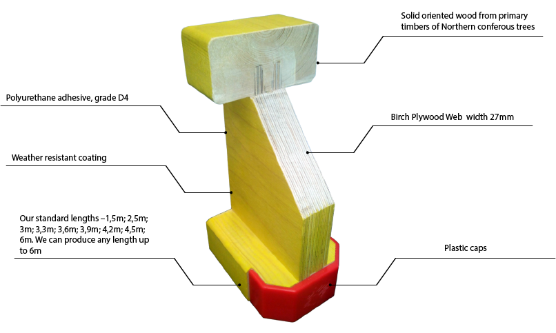
Herhangi bir döşeme formundaki zemin kaplamasındaki hem birincil hem de ikincil H20 Keresteleri, pişirilmiş suya dayanıklı tutkalla sabitlenmiş masif ahşap flanşlara sahip üç katmanlı masif ahşap köprü ile yapılır.


Uzun Ömürlü
Yuvarlak kiriş ucu koruma kapağı ile neme ve UV radyasyonuna karşı etkili koruma.


h20- ahşap kalıp kirişleri
- Farklı betonarme kalıp sistemlerinde kolay entegrasyon sağlar, projelere esneklik kazandırır.
- Geleneksel ahşap malzemelere kıyasla çok daha uzun ömürlü ve dayanıklıdır.
- Üretim kesitleri standart olup, projelere özel uzunluklarda üretilebilir.
- Ağırsız koşullarda bile şeklini bozmadan uzun süre dayanıklılığını korur.
- Kaliteli yapıştırıcılar kullanılarak uzun ömürlü ve güvenli bir yapı sunar.
- Yuvarlak uç tasarımı, kırılma riskini minimize eder.
- Hafif yapısı sayesinde taşıma ve montaj işlemleri son derece kolaydır.
- Her türlü inşaat projesine uyum sağlayacak şekilde tasarlanabilir.
- Betonarme döşeme, perde ve kolon kalıplarında sorunsuz kullanılabilir.
- Uzun kullanım ömrü ve sağlam yapısıyla ekonomik bir tercihtir.
- Üretim boyutları sabittir, bu da kolay kullanım ve planlama imkânı sunar.
- Hem çevre dostudur, hem de orman kaynaklarını korur, sürdürülebilir bir seçenektir.
H20 Ahşap Kiriş Kesme ve Eğilme Yük Tablosu

SIK SORULAN SORULAR
AMAÇ
Ahşap lamine I-kiriş BDK 1, zemin arası tavanların monolitik betonarme yapılarının inşası ve montajı sırasında donatı ve beton döküm işlemleri için kalıp elemanı olarak tasarlanmıştır. Bu sistem, dikey yüklerin emilmesini sağlarken, aynı zamanda yatay düzlemi hizalamak amacıyla jeodezik ölçüm ve ayar işlemleri yapar.
Kiriş, I şekline sahip olup, rafı oluklu iğne yapraklı ağaçtan üretilmiştir. Rafın uzunluğu boyunca zıvana bağlantıları olabilir. Stand FSF kontrplak kullanılarak, oluklar içinde dişli zıvana ve poliüretan yapıştırıcı ile montaj yapılmıştır. Kiriş, su itici özelliklere sahip su bazlı boyalarla kaplanmıştır, sarı GA 20054 rengi ile boyanmıştır.
Kirişin uçları, yüksek mukavemetli plastik uçlarla güçlendirilmiş olup, dayanıklılığı artırılmıştır. Kiriş, GOST 9463 standardına uygun olarak II. sınıf iğne yapraklı ağaç malzemesinden ve GOST 3916.1 ve GOST 3916.2’ye uygun kontrplaktan üretilmiştir. Ayrıca, kiriş özel teleskopik standlar üzerinde montelenir ve sabitlenir.
ANA TEKNİK ÖZELLİKLER
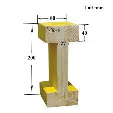
1.1 BDK 1 Kirişinin Ana Boyutları:
- Uzunluk (mm): 1500 – 6000
- Yükseklik (mm): 200 – 240
- Raf Genişliği (mm): 80
- Raf Kalınlığı (mm): 40
- Kontrplak Kalınlığı (mm): 27
- Kontrplak Dişi Kesme Derinliği (mm): 20
1.2 Geometrik Boyutlardan ve Şekilden Maksimum Sapmalar:
- 3,0 m’ye kadar uzunluk: ±4 mm
- 3,0 m’den fazla uzunluk: ±5 mm
- Yükseklik: ±2 mm
- Raf Genişliği: ±2 mm
- Raf Kalınlığı: ±1 mm
- Kiriş Eğimi: ±2 mm’den fazla olmamalıdır.
1.3 Düzlükten Sapmaların Sınır Değerleri:
- 3,0 m’ye kadar olan kiriş uzunluklarında: 4 mm’yi geçmemelidir.
- 3,0 m’den uzun kirişlerde: 5 mm’yi geçmemelidir.
- Düzlemden yükseklik sapmaları: 3 mm’yi aşmamalıdır.
- Bitişik yüzeylerin dikliklerinden sapmalar: 2 mm’yi geçmemelidir.
1.4 Kirişlerin Üretimi: Kirişler, belirtilen ve onaylanmış çalışma çizimlerine göre üretilmelidir.
1.5 Yük Özellikleri: EN 13377 standardına göre, kirişin yük özellikleri aşağıdaki gibidir:
- H 20
- Kesme Kuvveti (Vk): 23,9 kN
- İlave Yük (Q): 11 kN
- Bükülme Moment (Mk): 10,9 kNm
- İzin Verilen Bükülme Moment (M): 5 kNm
- Destek (Rb,k): 47,8 kN
- Elastik Moment ve Eylemsizlik Moment (EI): 486 kNm²
- Kayışın Elastikiyet Modülü (C24): 11.000 N/mm²
- Kaburganın Elastikiyet Modülü (SWP): 6.700 N/mm²
KİRİŞİN TESLİMAT SETİ
2.1 – FSF Kontrplaktan Yapılmış Kiriş BDK 1 (Enine Çubuk) Sehpası:
- Pasaport
2.2 – Teslimat Seti: Teslimat seti, bu pasaportta belirtilen standartlara uygun olarak sağlanacaktır.
GÜVENLİK TALİMATLARI
3.1 Güvenlik Gereklilikleri ve Çevre Koruma: Ürünlerin üretimi, mevcut teknik belgelere, inşaat kurallarına ve yönetmeliklere, ayrıca sağlık ve hijyen standartlarına uygun olmalıdır. Bu belgeler, sağlık yetkilileri tarafından onaylanmış olmalı ve çevre koruma ile ilgili gerekli prosedürler de içermelidir.
3.2 Ürün Üretimi: Ürünler, GOST 12.2.003-91 standardına uygun olarak üretilmelidir.
3.3 Yükleme, Depolama ve Boşaltma Güvenliği: Kirişlerin yüklenmesi, depolanması ve boşaltılması sırasında, GOST 12.3.002-75 “SSBT’ye uygun donanım ve kaldırma işlemleri için güvenlik kurallarına sıkı sıkıya uyulmalıdır. Üretim süreçlerinde genel güvenlik gereksinimlerine riayet edilmelidir.”
3.4 Teknolojik Süreç ve Güvenlik: Teknolojik sürecin organizasyonu ve yürütülmesi, çalışan personel, yakın çevredeki yerleşim alanları ve çevre için güvenlik önlemleri ve zararsızlık ilkelerini içermelidir.
3.5 Yangın ve Patlama Güvenliği: Üretim süreci, yangın ve patlama risklerine karşı dayanıklı olmalı ve gerekli tüm önlemler alınmalıdır.
3.6 Üretim Ekipmanı Güvenliği: Üretim ekipmanları, GOST 12.1.018-93 “SSBT’nin gerekliliklerine uygun olmalı, yangın güvenliği, elektrostatik iç güvenlik, koruyucu topraklama ve topraklama gibi önlemleri içermelidir. Ayrıca, GOST 12.1.045-84 standardına uygun olarak elektrostatik alanlarda işyerlerinde izin verilen seviyeler ve izleme gerekliliklerine de riayet edilmelidir.”
3.7 Kaldırma İşlemleri Sertifikalandırma: Madde 4.3’e göre, kaldırma işlemleri gerçekleştiren kişiler, bu işlemleri yürütme konusunda sertifikalı olmalıdır.
3.8 Kiriş Kaldırma ve Depolama Güvenliği: Kirişlerin kaldırılması, indirilmesi, kurulumu ve depolanması sırasında ani sarsıntılar ve darbelerden kaçınılmalıdır. Ağırlık kaldırma işlemleri, en az iki sertifikalı sapan ile yapılmalıdır.
3.9 Sapan Güvenliği: Kirişlerin kaldırılması, yüklenmesi ve boşaltılması sırasında kullanılan sapanlar, hasarı önlemek amacıyla brandaya sarılmalı veya yangın hortumundan geçirilmelidir. Çıplak kabloların kullanılmasına kesinlikle izin verilmez.
KABUL BELGESİ
4.1 Kirişlerin Paketlenmesi: Kirişler, paletler üzerinde paketlenmelidir.
4.2 Palet İçeriği: Her palet, aynı tipte kirişler içermelidir ve paletin ağırlığı 2 tonu geçmemelidir.
4.3 Teslimat Belgeleri: Her teslimat, bir pasaport ve uygunluk belgesi ile birlikte gönderilmelidir. Pasaportta şu bilgiler yer almalıdır:
- Kiriş tipi
- Miktar
- Boyut
4.4 Paletlerin Standartlara Uygunluğu: Paletler, GOST 19041-85*E gerekliliklerine uygun olarak üretilmelidir. Paletlerin genişliği 1350 mm’yi, yüksekliği ise 1450 mm’yi geçmemelidir.
NAKLİYE VE DEPOLAMA
5.1 Taşıma:
Kiriş paletleri, GOST 19041-85 gerekliliklerine uygun olarak her türlü taşıma aracıyla taşınabilir.
5.2 Depolama:
Kirişler, tür ve boyutlarına göre sıralanarak depolanmalıdır. Sarkma ve kalıcı deformasyonu önlemek amacıyla ahşap destekler üzerinde istiflenmelidir.
5.3 Taşıma Sırasında Koruma:
Taşıma sırasında kiriş paletleri, mekanik hasardan, nemden ve kirlenmeden korunmalıdır.
5.4 Kaldırma ve Yükleme:
Kirişlerin kaldırılması, yüklenmesi ve boşaltılması, özel kavrama cihazları ve esnek kayışlar kullanılarak bir vinç ile yapılmalıdır.
5.5 Yükleme ve Boşaltma Yasakları:
Yükleme, taşıma ve boşaltma işlemleri sırasında ürünlerin boşaltılması kesinlikle yasaktır.
5.6 Depolama Koşulları:
Depolama, yağışa ve doğrudan güneş ışığına maruz kalmadan kapalı, havalandırılan odalarda veya gölgelik alanlarda yapılmalıdır.
5.7 Temizlik:
Ürünleri temizlemek için aşındırıcı maddeler içeren deterjanlar kullanılmamalıdır.
5.8 Depolama Sırasında Renk Değişikliği:
Depolama sırasında, ürünlerin ışın rengi değişebilir.
ÜRETİCİ GARANTİSİ
Üretici, ürünlerin kalitesini ve standartlara uygunluğunu garanti eder.
ÜRETİCİ GARANTİLERİ
6.1 Üretici Garantisi:
Üretici, tüketicinin ürünlerin taşıma, depolama, kurulum ve çalıştırma koşullarına uygun olarak kullanılması durumunda, kirişlerin bu teknik spesifikasyonlara uygun olacağını garanti eder.
KİRİŞİN ÇALIŞMASI SIRASINDA İZİN VERİLEN KUSURLAR
A) Eğik Çatlaklar (Lifler Boyunca):
- İzin verilmez:
- Düz çatlaklar (Tane Boyunca):
- a = 2 mm’ye kadar flanşa paralellik izni verilir.
- Çatlaklar nedeniyle rafın genişlemesine izin verilmez.
- Düz çatlaklar (Tane Boyunca):
B) Yanal Soyulma:
- a = 10 mm derinlik ve 500 mm’ye kadar b genişlik için bir tarafta izin verilir.
C) Kenarda Eğik Soyulma:
- Çapraz olarak a = 30 mm’ye ve uzunluk b = 500 mm’ye kadar izin verilir.
D) Kesimler:
- a = 2 mm derinliğe kadar yüzey kesimlerine izin verilir.
E) Raf Sonu:
- 60 mm uzunluğa kadar soyulma kabul edilebilir.
F) Duvar Hasarı:
- Yalnızca küçük bir dereceye kadar ve kirişin yalnızca bir tarafında izin verilir.
G) Duvarın Ucundaki Hasar:
- Maksimum a = 20 mm derinliğe kadar izin verilir.